Bob Clarke’s 1965 MAD Zeppelin: The Assembly Continues
Putting the Ship Together (Figures 4-7)


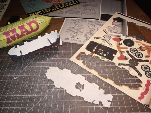
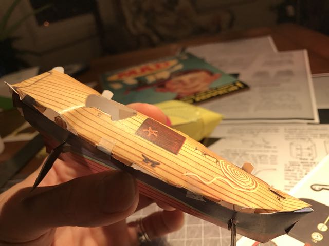
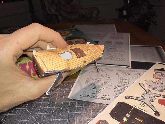
FIGURE 4: ATTACH DECK UNIT
Looking at the Deck and Hull Units, one can easily see that the outer edges of each part are mostly tabs and slots. Clarke chose not to include an illustrative figure to show these two parts connecting. We will never know why he thought the super-easy Figure 3 needed to be illustrated when I had major struggles putting the Deck Unit into and on the assembled Hull.
I think one difficulty for me was the fact that I made the color copies of the MAD Zeppelin with basic 20lb copy paper. TIP: At this point, I realized that I should have used a heavier stock of paper that was similar in weight to the paper stock of the original insert.
My copy Zeppelin felt very fragile at this stage of assembly, and it got more delicate and precarious for the final bits of assembly. TIP: I had to make the cuts on the tabs (Tabs P and Q) of the Hull and Deck deeper in order to make these pieces insert in a way that didn’t keep the deck from popping up and out. TIP: As you can see from my photos, I put small pieces of tape over the middle connections of these two parts. They kept popping out as I tried to work the end tabs. Not pretty, but it keeps things together.
FIGURE 4 is basically pushing in the the stern parts together to make the back of the MAD Zeppelin’s ship. It didn’t fit together that well, so I compensated by dropping a bit of glue and then pinching the two parts of the hull together just aft of Slot V.
This is starting to look like a real version of the famous MAD Zeppelin.
FIGURE 5: THE BOW UNIT
As I said in my introduction, I was going to go step-by-step in the order that Clarke listed. For this stage, I unknowingly cut out the Rudder before the Bow and Mast. A small misstep that caused no harm. I then cut out and installed the Bow Unit. These were all easy parts to install, so I am not sure why Clarke made an illustration for the Bow Unit.
The Mast Unit install became tricky, again due to the 20lb copy paper. I only realized, after inserting the Mainsail and Flag, that the Mast needed to be sturdier. But I’m getting ahead of myself.

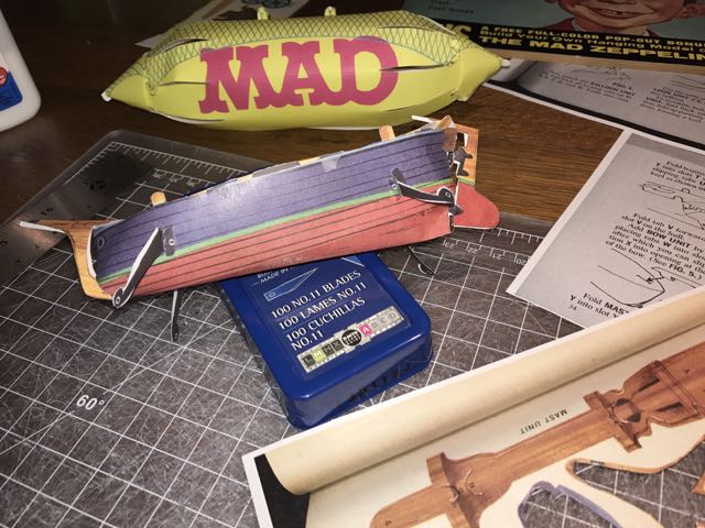
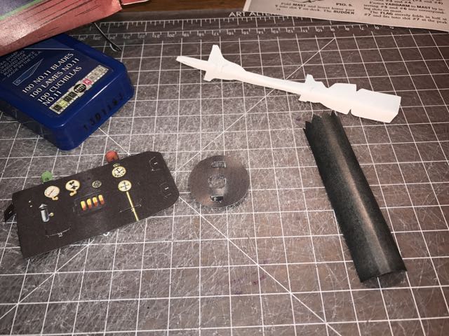

FIGURE 6 and 6a: THE BOILER UNIT
The Boiler Unit was very fun to cut and install. Clarke’s design skills shine on this part of assembly, especially with the black Stack. “Roll it around a pencil” and simply stick it into the top of the Boiler (and down into the Hull). I installed this with the Boiler Unit, which is out of the order that Clarke gave. TIP: Don’t forget to bend back the pointy parts at the top. The complete Boiler looks realistic, even with imagined smoke coming out.
After this part, The Yardarm and Flag get put on the mast. Arrrgh! I should’ve made copies with heavier paper. The Mast had problems holding these two parts. I had to use small bits of tape to make it work. TIP: I glued the Flag together (pre-folded first).
By now, the ship looked great. Almost done! But it was very light and delicate. I had to be very careful. The Wheel Struts kept moving around, but were easy to pull back in place. Parts kept falling off and needed to be put back on. I wondered if the original parts were as delicate.
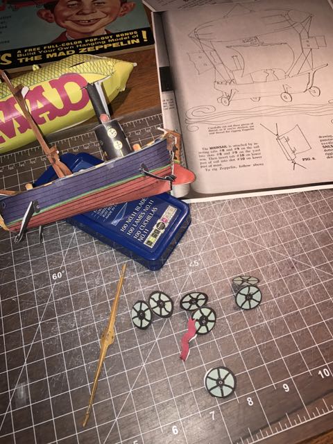
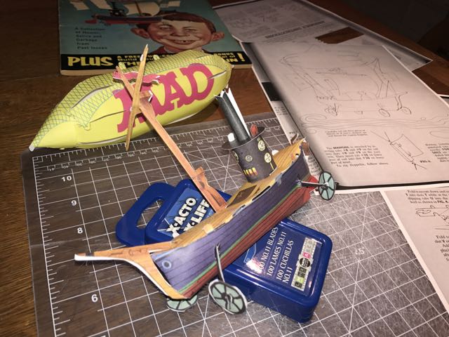
FIGURE 7: THE WHEEL STRUTS
Another easy step that didn’t need an illustration. After folding the wheels, I glued them together. For my copy, they fit loosely on the struts – delicate and easily messed up since they will fall off. But also easily fixed.
After all this assembly, the instructions state that “THERE ARE NO MORE PIECES LEFT AND THE ZEPPELIN IS STILL INCOMPLETE.” If you look at your copies, you’ll see that you have to cut the sails out. Clarke tells us to cut these out at the beginning, but I waited until now. Not a problem….
Coming soon: The Final Set of Assembly Instructions (or, time to get some string on)!